The boss may think it only takes 5 minutes to program a taper scan, but we know it takes more time than that to get the job done properly. We’ll show you the whole process of measuring a taper, plane and circle on a tool with unique dimensions with a CMM and PC-DMIS CAD++.
Video Transcript:
“Hey Ethan, how are you doing, man?
Oh great.
Do me a huge favor. Can you scan the taper on that tool holder for me?
Of course!
Should only take about five minutes, right?
Only five minutes? Yeah.
Appreciate it, man.
I hate that saying: “only takes five minutes.” We all know it never does. Today we’re gonna set up a scan on the taper of a tool holder. If it takes five minutes, maybe the boss was right for the first time. Or if not, we’ll have to lie to him again.
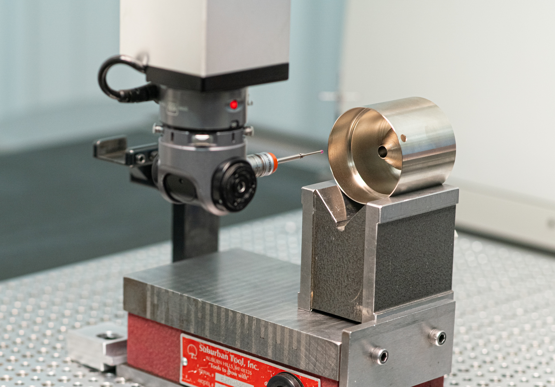
All right. For the first step that we’re gonna do to scan that taper, let’s bring in our CAD model. We have the program up already. We’ll click our CAD button here. Find the appropriate file and import that in. Now we have our model in here and we’re going to tell the machine where that part’s gonna sit. We’ll do our manual touches. We’re gonna say we’re gonna hit here, here, and here. That’ll make our first plane.
Now we’ll make a circle. The computer will suggest certain ways to look at this part so it knows that it’s looking at it appropriately. One more.
Of course it’s going to give me grief. That’s why it never takes five minutes.
If you’re having issues trying to build a plane and it keeps showing up as a line, double check your view and make sure that you’re in the appropriate view. Now this is how the program is going to look at the part. Whether we’re going to be looking at from the y-axis, along the x-axis, or along the z-axis. How you look at the part is how the computer is going to be looking at the part as well.
Now that we have some of those features touched of, or told to be touched off, we’re going to align this part. Now this initial alignment is just telling the machine where the part is going to be in the space, and how it’s going to be oriented. We want the machine to come in and touch the part the right way and not crash into it. That doesn’t make the boss happy. You select those features. I like to use the auto-align feature especially for initial alignment.
Now that our alignment’s in, the part is going to link to the CAD so the machine knows where it’s at right now and how it’s going to go. We’re going to use our job box. We’ll start our program, and it’ll tell us where it wants us to hit. We’ll touch this first plane. Remember when you’re building planes: you want to use triangles. So those were our three hits for the plane. It’ll say end plane feature, and we’ll hit the green button. Now our next feature will be the circle. Again once we hit it an appropriate amount of times, it’ll tell us to end that feature. We’ll hit the green arrow. Onto the third and last one.
And with that, now the part is synced with the program and the CMM. As the probe shows where it’s at on the part with the CAD model, the probe is in the exact same spot on the physical part.
Now that we’ve done the manual alignment, let’s add an auto alignment. This will give the CMM the capabilities of touching the part in the exact same spots every time so it’s going to align that part just perfectly. We’ll use the same features that we use for the manual. We’re gonna add a change our probe mode to DCC mode, which is auto mode. We’re going to highlight, you hold shift, highlight the feature, and now we have a plane.
We’ll get that circle built. We have the circle, and the plane. We have to polish this up so let’s make sure it’s going to touch in the right spots. This first plane will add a boundary that’s about 1.5 millimeters off of its edges, so we’re not going to touch anything that’s going to get us in trouble.
The circle–I was a little far off so let’s move it back onto the part.
Let’s make sure we’re not going to hit our fixturing. You can drag and move the areas in which you want it to scan.
We’ll do four hits on this one. So our circle is set up, and our last plane. Now we don’t want to be too close to these edges. You don’t want to crash the machine, that’s never fun.
We’ll add another boundary offset. Now we’re far away from those features. We’ll add our alignment. Three, four, and two. Now we have the machine aligning itself, and the most important thing that we’re going to do is check our moves. You don’t want the machine to try and go through the part! You want it to go around the part.
We’ll highlight those three features. Right click, go to path, and select path lines. This will show all the areas in which the part or the machine is going to move. As you can see here, that’s not going to work. We can’t go through the part.
Find a good angle to change it. Click on your path line, and then you can adjust using your axis.
That one avoids the part, we’re good on that move. And we have one more here that we’re gonna have to fix.
Now we have all of our moves that will be clear of the part so it won’t crash the probe. What I normally do with this is I like to run this just to make sure everything’s going to go right before I continue with my program. So let’s run it and double check it.
Now we have our manual alignment and our auto alignment, we’re ready to get that taper going. So for the taper, we’re going to check this cone here. We’ll hold shift, it’ll highlight that whole feature, and we can click on that. Then we’ll adjust it from here. We’ll click ok and open it up. This is a traditional touchpoint. We want to change that to one of our three scans that we can do. Let’s do a concentric circle scan today.
We will make sure that we’re not going to go through the part again, so I’m going to change some things around.
We just shifted our Angle. Now we’re going to start scanning from the top instead of having to come around to the bottom of that part. We’ll only do two rows today.
So we have our two rows of our scan that we want to set up.
Now we can see our avoidance moves. They’re going to put us in the middle of the part, so I’m going to manually do that myself. Let’s check our move.
We’re good.
Now one thing that I didn’t change that would have hurt me very bad: I didn’t change the probe tip! We’re going to tell the CMM to use a different probe tip instead of the one we’ve been using this whole time.
Now with this fixed head CMM, we like to use the star tips. In order to remember the numbering on the star tips, I’ll go over them. The bottom is number one. Number two, number three, number four, and number five. For the scan we’re going to be using tip number two. So we’ll do that at the top of our screen, we’ll change that to tip two. Now when you change the tip like that, again you want to watch your moves. Make sure you’re not going to crash through the part.
Let’s keep this one high because that number one probe will end up going through the part if we let it go to where it wants. Now that we avoided the part, we should be good to go. We can get this cone scan, and we’ll get [the boss] his data. We’ll click on our feature location, click on our cone, and we’ll give them the angle today.
You want to double check your tolerances. Create that. If your CAD model is right, it should say passed. Our CAD models are correct, we’re passed. That where we’re at right now, so let’s run the part/make sure it’s good.
Now that that program’s done, let’s check our results. This [part] calls for a 16.5 degree taper. We measured it at 16.58 which keeps us right in tolerance.
All in all, this took about 15 minutes. We’ll tell Mike it took five. He’s bad at time anyway.”